

A furnace starts on a cold morning. You hear the ignition sequence, the burners light, and warm air begins moving through the house. Hidden inside the unit, a small flame sensor checks whether combustion is present. If the flame disappears, the sensor helps the control system stop the fuel flow instead of allowing unburned gas to continue accumulating.
The same basic question appears in a refinery burner, process heater, boiler room, or other industrial installation: is there a real flame right now? The answer may come from ultraviolet radiation, infrared radiation, flame ionization, or a combination of signals. The hardware changes with the application, but the safety purpose stays narrow and important.
This guide follows the signal from radiated energy to an electrical decision, then explains the main sensor types, residential flame-rod readings, placement limits, missed fires, and nuisance alarms. It also treats flame sensing directly. A flame sensor is fast and useful, but it isn't a universal fire detector.
The Moment a Flame Sensor Quietly Matters
A residential furnace can appear to work normally from the outside. The thermostat calls for heat, an igniter starts the burner, and the control board waits for proof that the gas has lit. The flame sensor acts as the quiet witness. It doesn't decide whether the room feels warm, and it doesn't measure the temperature of the heat exchanger. It confirms that the fuel being released is burning.
Industrial systems use the same logic under harsher conditions. A detector may watch a burner from across a process area, looking for the radiation pattern associated with combustion. If the flame fails, the safety system can close the fuel valve and place the equipment in lockout rather than allowing the process to continue blindly.
One question, several technologies
The question is simple, but the answer isn't always based on visible light. Modern flame sensors detect radiation emitted during combustion, most often in the ultraviolet, infrared, or both bands. Industrial literature distinguishes these bands from visible light, which spans roughly 4000 to 7000 angstroms, because flame detectors are engineered to monitor wavelengths outside normal human vision. Many UV sensors operate around 295 to 320 nanometers, while UV/IR systems may require both channels to exceed set thresholds before generating an alarm. (Historical development of fire detection systems)
A residential flame rod works differently. It uses the flame itself as part of a tiny electrical circuit. The flame's ionized gases allow a control board to verify combustion through a small direct-current signal.
Practical rule: A flame sensor isn't trying to understand fire the way a person does. It's checking whether a narrowly defined physical signature is present and trustworthy.
Why milliseconds matter
A detector must respond quickly because fuel and combustion systems don't have the luxury of waiting for a visual inspection. Some modern solid-state flame sensors can respond in under 25 milliseconds, and high-speed detectors may be specified below 15 milliseconds under ideal conditions. (Industrial flame detection technical paper) That speed supports the safety function, but it doesn't remove the need for correct sight lines, suitable calibration, grounding, and maintenance.
The rest of the system turns that small observation into action. A sensor detects energy or ionization, electronics condition the signal, logic verifies it, and a relay or safety output tells the fuel-control system whether operation may continue.
The Physics of Flame Radiation
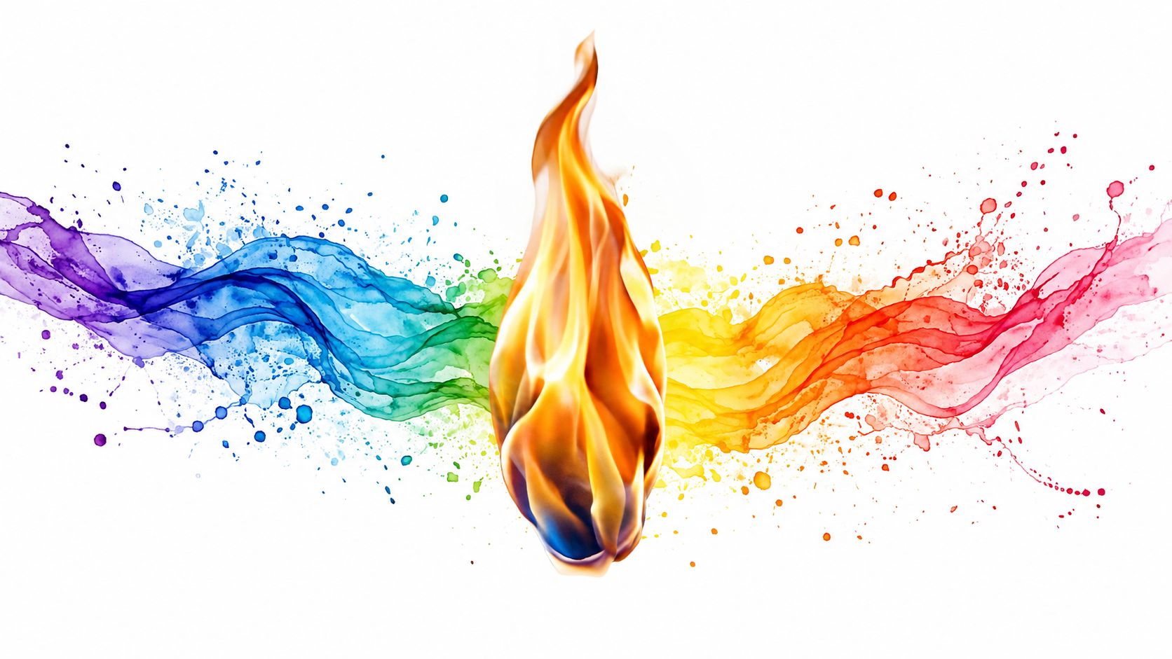
A burner can look steady to your eyes while its detector receives a changing mix of invisible and visible energy. Combustion releases chemical energy, and part of that energy leaves the reaction zone as electromagnetic radiation. A flame therefore resembles a lamp with many wavelengths, rather than a light source with one clean color. Different parts of that spectrum reveal different features of combustion.
Ultraviolet radiation can arise from energetic chemical reactions and excited species in the flame. Visible light often comes from glowing soot or incandescent particles. Infrared radiation comes from hot combustion products, including gases that emit strongly at characteristic wavelengths. This broad output gives engineers several physical signals to monitor, while also creating possible sources of confusion.
A sensor works like a tuned eye
Human vision is limited mainly to visible light. A person may see a blue or yellow flame and expect a detector to respond to that appearance, but the detector usually measures a narrower signature. It monitors a selected wavelength, or a combination of wavelengths, and checks how the signal changes over time.
Common industrial designs target flame-related regions such as UV bands around 185 to 260 nanometers or infrared energy around 4.3 micrometers. Some also examine flicker in the 5 to 30 hertz range. (Industrial flame-detection catalog) The question is not whether light is present. The electronics look for radiation with the spectrum and time pattern expected from combustion.
Why wavelength selection reduces confusion
Sunlight, hot surfaces, lamps, reflections, sparks, and welding arcs can all reach an optical detector. Cooking aerosols and smoke can also scatter or obscure the signal. A broad, unfiltered sensor may therefore respond to the surroundings, miss a partially hidden flame, or struggle to distinguish a burner from another bright source.
Engineers reduce these errors through several forms of selectivity:
- Spectral filtering restricts sensitivity to a useful wavelength range.
- Dual-band comparison checks whether two channels behave consistently.
- Flicker analysis examines the changing intensity associated with an open flame.
- Threshold logic requires adequate signal strength for an adequate time.
The design depends on fuel, burner geometry, background radiation, and the required safety response. Placement matters just as much. A sensor needs a clear view of the part of the flame that produces its intended signature, while heat, dirt, condensation, and obstructions can weaken that view.
A small module may use an infrared photodiode and threshold circuit. An industrial detector may combine optical filters, multiple sensing elements, signal processing, diagnostics, and a safety-rated output. Neither device recognizes “fire” as a universal category. Each responds to a defined radiation pattern, so smouldering material without an active flame can remain outside its detection range.
Three Ways a Sensor Detects Flame
A furnace can shut off even while heat remains nearby, because its control system needs evidence of an active flame, not merely a hot surface. Flame detection uses three main physical principles: ionization, ultraviolet detection, or infrared detection. Each asks a different question about combustion, so fuel, burner design, viewing conditions, and the required response all influence the choice.
| Principle | Ionization (Flame Rod) | UV Sensor | IR Sensor |
|---|---|---|---|
| What it detects | Electrical current through ionized flame gases | Ultraviolet photons emitted during combustion | Infrared radiation from flame and hot combustion products |
| Typical use | Burner flame proving in residential and packaged combustion equipment | Fast open-flame detection where UV selectivity is useful | Small modules and industrial flame monitoring |
| Main strength | Direct confirmation at the burner | Fast response and sensitivity to flame-specific UV | Stand-off detection and spectral or flicker analysis |
| Main limitation | Works only when the electrode sits in a conductive flame | Needs a clear optical path and can face nuisance radiation | Can respond to non-fire IR sources without careful filtering |
| Signal form | Tiny DC current, measured in microamps | Photocurrent or processed optical signal | Photodiode, pyroelectric, or thermopile output |
Ionization through a flame rod
A flame rod is a metal electrode positioned so the burner flame touches it. Combustion creates ions and electrons in the flame, allowing the gas to conduct electricity. The control circuit applies an alternating electrical potential. Because the flame conducts differently in each direction, its geometry produces rectification, leaving a small DC current that the control board can measure.
The rod works like a continuity check through the flame. It does not measure heat by itself, prove that the burner has reached the correct temperature, or confirm combustion when the flame does not physically contact the sensing area. Its strength is direct confirmation. In a furnace, the signal comes from the actual burner flame rather than from a distant optical view.
Ultraviolet detection
UV detectors use a UV-sensitive tube, photocell, or solid-state element to detect photons within a selected ultraviolet band. Historical designs used Geiger-Mueller-type vacuum tubes sensitive to approximately 1850 to 2450 angstroms, with some models extending to 2650 angstroms. Modern systems may use solid-state devices and signal processing for rapid confirmation. (Technical history of flame detection)
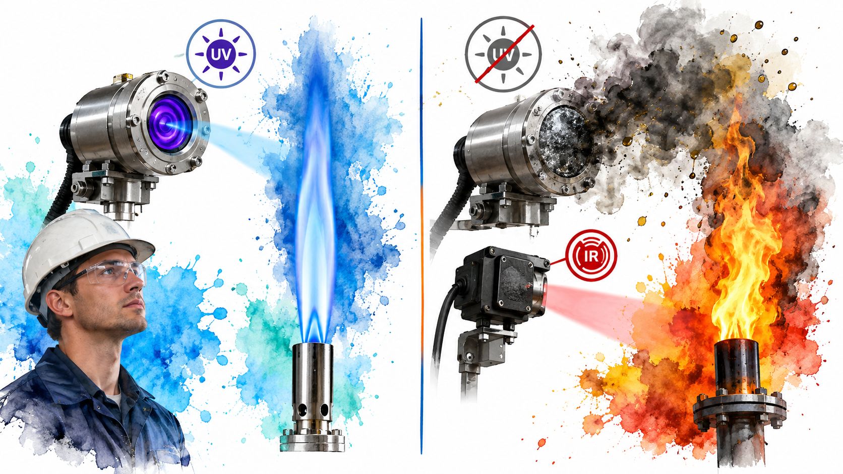
The useful analogy is a color filter that accepts a narrow clue rather than all visible brightness. Many ordinary background sources produce little useful energy in the selected UV band, which can improve discrimination. A clear optical path still matters. Soot, oil mist, dirty windows, or an obstructed sight tube can weaken the signal even when combustion remains healthy. A smouldering material with no active flame may produce no suitable UV signature.
Infrared detection
IR sensors use an IR photodiode, pyroelectric cell, or thermopile to detect energy emitted by a flame. Many small modules monitor roughly 760 to 1100 nanometers, use a field of view near 60 degrees, and respond in under 15 milliseconds to about 100 milliseconds. Their practical stand-off distance may range from centimeters to about 1 meter, depending on flame size and optics. (LM393 flame-sensor module reference)
Industrial IR detectors may sense a narrow band around the 4.3 micrometer combustion signature, compare multiple wavelengths, and examine flicker. Those measures can help distinguish a flame from a hot object, although sunlight, heated equipment, reflections, or cooking aerosols can still create nuisance signals or obscure the view if the detector is poorly placed.
The trade-off is clear. Ionization proves a burner flame at the electrode. UV can respond quickly to a flame-specific optical signature. IR can watch an open flame from a distance, but reliable protection depends on the sensor seeing the intended flame while limiting competing radiation. A detector aimed at a wall, blocked by equipment, or exposed to a strong nuisance source cannot compensate through sensitivity alone.
From Light Signal to Lockout Decision
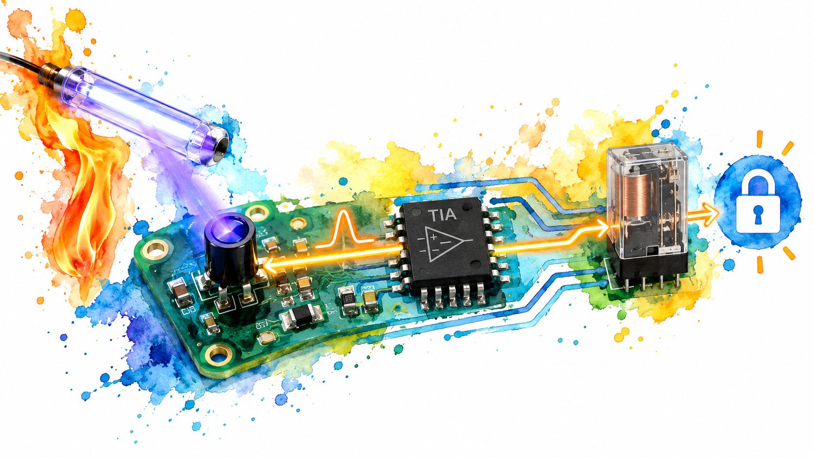
A flame detector does not pass raw radiation straight to a fuel valve. It first converts incoming energy into an electrical signal, conditions that signal, checks whether its behavior matches a flame, and then permits operation or commands a safe shutdown.
A simple optical chain starts with a photodiode or UV tube. Photons produce a small current, and an amplifier, often a transimpedance stage, converts that current into a voltage that control electronics can interpret. Filters remove steady background radiation and frequencies outside the detector's intended flame-analysis range.
The logic has several gates
Signal strength alone may not be enough. A control circuit or microcontroller can check whether the signal is present, whether it flickers in a flame-like pattern, whether separate channels agree, and whether the detector's self-test shows a healthy condition. This layered approach helps reject a bright reflection, sunlight, or a brief spark.
The decision path usually follows these stages:
- Capture: An optical element or flame rod receives a physical signal.
- Condition: Amplifiers and filters make the small signal usable.
- Analyze: Logic checks magnitude, timing, flicker, or agreement between channels.
- Verify: The system holds the signal for the required confirmation interval.
- Act: A relay or safety output permits fuel operation, or initiates lockout.
Industrial detectors can be tested against defined fires at long stand-off distances, with response depending on the detector, target fire, optics, and test conditions. (Flame-detection performance catalog) Residential controls use a different signal path, but the safety principle remains the same: fuel operation requires verified combustion.
The relay should close only after the evidence passes the system's rules.
The logic must also remove run permission quickly when the flame signal disappears. A lockout is the protective action that prevents continued fuel delivery without confirmed combustion. Its effectiveness still depends on placement. A blocked view, a detector aimed away from the hazard, or an optical path clouded by smoke and deposits can prevent valid evidence from reaching the decision circuit.
Wiring and Reading a Flame Signal
A residential furnace flame rod offers the clearest example because the sensor's job is easy to visualize. The rod sits in the burner flame, one wire connects it to the ignition control, and the burner chassis provides the reference path. When the flame is present, ionized gases conduct a small rectified DC current back to the control board.
The control circuit is powered as part of the furnace's low-voltage and ignition system. In a common arrangement, the flame-sensor lead runs to the ignition module, the burner assembly provides the ground reference, and a 24 VAC transformer supplies control power. The exact terminal layout varies by equipment, so technicians should follow the manufacturer's wiring diagram rather than relying on wire color.
Reading the microamp signal
A meter measures the flame signal in series, not across the sensor like a normal voltage measurement. The technician disconnects the sensor lead, inserts a meter set for DC microamps, and observes the reading during the ignition sequence. Work on gas-fired equipment requires appropriate isolation, safe procedures, and manufacturer-specific instructions.
Typical residential flame-sense readings are often around 2 to 6 microamps DC. Many systems treat approximately 1 microamp DC as a minimum proof-of-flame threshold, while readings below roughly 0.5 microamps are often associated with immediate lockout or shutdown. (Residential flame-sensor microamp reference)
| Sensor Type | Healthy Reading | Weak/Lockout Reading | Test Method |
|---|---|---|---|
| Flame rod | Often around 2 to 6 microamps DC | Around 1 microamp may be a minimum threshold, and below roughly 0.5 microamps may cause shutdown | Inline DC microamp meter |
| UV detector | Processed optical signal meeting configured verification limits | Signal below the configured flame threshold | Manufacturer-approved test or diagnostic procedure |
| IR detector | Processed IR signal meeting configured verification limits | Insufficient or inconsistent optical signal | Manufacturer-approved test or diagnostic procedure |
A weak reading doesn't automatically mean the rod itself has failed. Dirt, poor grounding, damaged wiring, weak combustion, or incorrect flame contact can produce the same symptom. Cleaning the metal rod with fine steel wool may restore a marginal signal, but repeated lockouts deserve a full inspection rather than repeated resets.
Industrial UV and IR detectors commonly use shielded cabling and a separate flame amplifier or controller. The hardware is more specialized, yet the underlying pattern remains familiar: measure a small signal, compare it with a defined threshold, and remove fuel permission when the evidence no longer supports continued combustion.
What Flame Sensors Catch and What They Miss
Flame sensors are good at one task: recognizing open combustion that produces the expected optical or electrical signature. They aren't universal fire detectors. A smouldering mattress, glowing insulation, or hidden ember may release heat and smoke without producing a flame that an optical detector can see.
That limitation creates an important distinction between flame proving and fire detection. A flame rod can confirm a burner only when the flame reaches the electrode. An optical detector can monitor a larger area, but only if the flame remains visible through a suitable line of sight.
Match the sensor to the combustion
UV, IR, and ionization methods each have boundaries.
- UV sensors can respond quickly to suitable hydrocarbon and hydrogen flames, but soot, oil mist, dirty optics, and obstructed viewing windows can weaken the signal.
- IR sensors work well for many hydrocarbon fires, yet some blue or low-radiation flames may be harder for a particular detector to recognize.
- Ionization rods work only where a pilot or main burner creates a conductive flame across the electrode and burner ground.
The phrase “can detect flame” therefore needs context. Fuel chemistry, flame color, pressure, burner shape, background temperature, and optical access all influence the result.
Placement determines coverage
A detector can't protect what it can't see. Distance, flame size, mounting angle, field of view, reflections, smoke, and physical obstructions all affect performance. Larger or divided spaces may need multiple detectors because one unit's line of sight can leave blind areas. (Analysis of flame-sensor limitations)
A practical installation review should ask:
- Is the likely flame location visible from the detector?
- Can equipment, ductwork, walls, or stored materials block the view?
- Could a reflective surface redirect radiation into the detector?
- Does the detector's field of view cover the entire hazard zone?
- Will smoke, dust, steam, or oil deposits contaminate the optical path?
A flame detector's coverage is a geometry problem before it's an electronics problem.
For life-safety coverage, pair flame detection with smoke, heat, or gas detection as appropriate. Flame sensing answers, “Is combustion present now?” It won't reliably warn about every fire that starts without an open flame.
False Alarms and Real-World Troubleshooting
A flame sensor can trip while a burner is operating normally. The detector may be responding to radiation or electrical conditions that resemble its target. Sunlight, lamps, sparks, reflective surfaces, dust, steam, and cooking aerosols are reported nuisance-alarm triggers for flame detectors. (Fire detection false-alarm research)
UV systems may react to intense sunlight or arc-welding flashes when filtering or shielding is inadequate. IR systems can respond to hot machinery, flickering lamps, or reflected radiation. In residential equipment, a contaminated flame rod, poor grounding, damaged wiring, or an unstable burner flame can weaken the signal and cause a lockout that resembles sensor failure.
Smouldering material creates a different blind spot. A sensor that relies on open-flame radiation may detect little or nothing until visible flame develops. For broader fire protection, another detection method may be needed.
Diagnose before resetting
Use the event history and the physical installation to narrow the cause:
- Optical interference: Add suitable filtering, shielding, or a sight tube that blocks unwanted angles.
- Wrong spectral response: Choose narrow-band or multi-band detection suited to the fuel and hazard.
- Dirty viewing path: Inspect and clean the lens or window according to the equipment procedure.
- Weak flame signal: Check burner condition, flame contact, wiring, grounding, and sensor contamination.
- Intermittent nuisance trips: Review sensitivity, verification timing, vibration, reflections, and recent environmental changes.
Multiple spectral channels and time-based analysis can distinguish a real flame from a brief flash or steady background source. AI and multi-stage verification are also being studied to reduce nuisance alarms. Results depend on the fuel, installation, calibration, and decision logic, so a more complex detector is not automatically better.
A lockout deserves a documented walk-through, not a blind reset. Record when it occurred, which nearby equipment was operating, what the flame looked like, and whether the optics, wiring, and diagnostics were healthy. Check obstructions and reflections from the detector's actual position. That record gives the technician a starting point for finding the cause and confirming that the protective function remains available.
Key Takeaways for Safer Flame Detection
Five principles keep flame detection grounded in real conditions:
- Match the detector to the fuel and combustion style. UV, IR, and ionization each depend on different physical evidence.
- Treat distance and line of sight as engineering variables. An obstructed or poorly angled detector can't provide reliable coverage.
- Verify signal strength during commissioning. Presence alone doesn't prove that the margin is healthy.
- Plan for cleaning, inspection, and recalibration. Dust, soot, oil, and aging can change the signal path.
- Don't treat flame sensing as universal fire detection. Pair it with smoke, heat, or gas detection when the hazard requires broader coverage.
A flame sensor answers one fast, narrow question: is combustion present right now? Fast electronics help, but safe operation still depends on correct installation, measured signals, sound lockout logic, and a technician who respects the data instead of bypassing the warning.
The Advertising Suite helps service businesses turn technical expertise into qualified demand through strategic creative, targeted advertising, conversion optimization, an integrated CRM, and review management. Visit The Advertising Suite to request a growth consult and build a results-first system that works as an extension of your team.
